
Your medical device has been designed and your preferred plastic has been selected. The final step is to mold your part, which should be simple. However, even the most seasoned injection molders face molding challenges, including medical device manufacturers.
Although these challenges are common in every industry, defects associated with medical devices require special attention to plastic material selection and part design along with the associated mold design and process parameters.
Medical devices are subject to stringent regulations, specifically FDA and ISO. Defects can seriously compromise the integrity of your final product and their subsequent approval. Fortunately, these challenges can be remedied and even prevented.
Causes of injection molding defects
Attention to detail as well as adhering to best practices can minimize and even prevent molding defects. The root cause of most molding defects can be narrowed down to issues associated with the machine, mold, plastic material and / or the operator.
Be mindful of oversights on these process parameters and considerations:
- Mold design
- Mold flow
- Venting
- Gating
- Plastic material
- Viscosity
- Hydroscopy
- Material handling
- Melting temperature
- Cooling temperature
- Temperature settings that are not optimized for the plastic material
- Mold temperature
- Melt temperature
- Pressure at different stages of the medical molding process
- Injection pressure
- Holding pressure
- Ejection pressure
Common medical molding challenges

Defects can range in seriousness from simple cosmetic blemishes to concerns with the part’s integrity. We have provided a list of 11 medical molding challenges along with their causes and remedies (see below). Although each defect varies in severity, we have categorized them based on whether they are a cosmetic or structural issue.
Cosmetic medical molding challenges
Cosmetic challenges generally do not affect the structural integrity of a part. However, they do affect the part’s aesthetics.

Splay
Splay is a common cosmetic defect that comes in the form of silver / white streaks on a part’s surface.
Causes: It generally occurs when a hydroscopic material has not been dried properly before the medical molding process.
Remedy: Conduct a moisture analysis to verify that your dryer is functioning properly (note that moisture can compromise a material’s properties). We strongly recommend conducting a moisture analysis at the start of every production run or if splay occurs.

Flow lines
Flow lines are streaks, patterns, circular ripples or lines that occur on the surface of a part.
Causes: Flow lines are caused by the varying speeds at which molten plastic flows when going around a part’s geometry. The disruption in the flow causes the plastic to solidify inconsistently. Note that the cooler the material, the longer the flow lines.
Remedy: You may need to increase the temperature of the mold and / or press to increase flow. Other remedies include increasing the injection speed and pressure.

Weld lines (knit lines)
Weld lines form on the surface of a part where two flow fronts meet. They tend to be the weakest point on a part since the two fronts were unable to “knit” back together properly.
Causes: Weld lines occur when an obstruction forces the plastic flow front to split and reknit again. If the plastic material doesn’t quickly reknit, the weld line will be more apparent.
Remedy: Be mindful of viscous plastics since their low melting points make them prone to weld lines. Increasing the injection speed at 10% increments as well as the temperature of the mold and / or press also helps. In addition, consider addressing your gate positions.

Flash
Flash takes on the form of thin plastic layers that have hardened outside of where the mold’s two halves (Part A and Part B) meet. You should fix flash immediately because it will damage your tool if it occurs over several cycles.
Causes: Flash is caused by plastic escaping from the mold cavity through a mold’s parting line, insert line or pin holes. This can be due to excess injection pressure or low clamp pressure (which keep both Part A and Part B together).
Remedy: Avoid overpacking the mold cavity and make sure the clamp pressure is strong. Also try to reduce your injection pressure and stay within the process window. Reducing the cycle time and barrel temperature can help lower the plastic’s viscosity.
Structural medical molding challenges
Unlike cosmetic challenges, structural challenges can seriously compromise the integrity of a part and render them unusable.

Jetting
Jetting comes in the form of a buckled, “snakelike” stream. It can lead to part weakness and internal defects.
Causes: Jetting results from plastic being pushed at a high velocity through tight areas in the mold without making contact with the walls. This can be due to excessive injection speeds, low mold temperature and improper gating.
Remedy: Optimize the plastic’s speed and gating for a consistent flow. Consult with a material supplier for a mold temperature that will facilitate a proper flow.

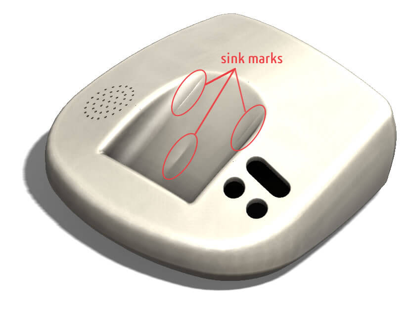
Sink marks
Sink marks result from shrinkage in the thicker sections of a mold and appear as depressions on the part.
Causes: Sinks marks are caused by differential cooling in the thicker wall sections, inadequate pressure in the mold or improper wall sections for protrusions on the part.
Remedy: Sink marks can generally be avoided with a part design that accounts for wall thickness (thicker ones have a longer cooling time). We recommend having a proper wall section to rib section ratio since protrusions in the mold tend to leave sink marks. Also consider increasing the holding time and lowering the mold temperature so the part can cool properly.

Vacuum voids
Vacuum voids are bubbles within a part that can weaken its integrity. They result from trapped air or differential shrinking.
Causes: Vacuum voids can be traced back to your wall sections. A mold’s steel is cooler than the molten plastic material, which creates a void because the outside is cooling faster than the inside.
Remedy: Increase the holding pressure and time so that the molten plastic can align with the mold’s walls.

Short shots
Short shots occur fairly often during a first run. As their name suggests, they are areas of the part where the plastic material has come short, leaving missing elements in the final part. They can also be an extension of flow lines and knit lines.
Causes: Molten plastic will naturally flow along a path of least resistance. However, it will stop at thinner sections if the holding pressure is too low. Low process parameters can also result in shorting.
Remedy: Have your plastic material undergo a validation process to ensure proper flow. Increasing the mold and / or press temperature, accounting for gas generation and increasing the material feed can also prevent short shots. Thin walled sections will need a material with increased flowability versus a thick walled section, which will work better with a stiffer material.

Warping
Warping is a dimensional deformation that results from uneven plastic shrinkage. Semi-crystallines are more likely to warp since they have specific cooling times. Note that glass-filled materials have a tendency to warp more than unfilled materials.
Causes: Warping can be caused by inadequate injection pressure, a low nozzle temperature, inadequate gating and issues with material flow. Note that warping generally occurs during cooling.
Remedy: Try to increase the cooling time to reduce residual stresses on the part and ensure the plastic is flowing in one direction so its molecules align. Proper gate positioning will also help with alignment. In addition, installing a nominal wall throughout your part will help the plastic cool consistently.

Burn marks
As the name suggests, burn marks are literally burns that occur on the surface of a part. They generally appear in blind pockets or at the end of the flow path.
Causes: Burn marks are caused by fast injection speeds, excessive heating and improper venting. Fast injections speeds and excessive heating without proper venting trap gases in the molding, causing the plastic to overheat and burn.
Remedy: Reduce the temperature of the mold and injection speed. Add additional venting and clean your vents regularly to prevent blockage.

Surface delamination
Surface delaminations are flake-like layers on a part’s surface that can reduce its strength.
Causes: Surface delaminations can occur if the molten material has cooled too fast while moving through the mold, hence forcing the plastic layers to solidify before they can fuse together. Material handling issues can also cause surface delaminations by allowing foreign material to enter the mold. The foreign material’s inability to properly bond to the plastic material can result in delaminations.
Remedy: Recheck your mold’s gating and reduce sharp turns in the part design; sharp turns can disrupt the mold flow and cause shearing. Confirm that the drying times and mold temperatures have been optimized for your plastic. You can also try increasing the injection speed at 2% increments. Lastly, check for contaminants in your plastic supply.
Medical molding considerations
Medical devices should be carefully designed so they are in line with regulations and optimized for injection molding. Adhering to proper Design for Manufacturing (DFM) practices reduces the risk of most defects. In addition, a material supplier can help you identify appropriate materials for your product design.
Staying within the range of your process parameters during the molding process will help prevent most defects. To this end, a process validation can help you establish a high and low range for critical process parameters. We recommend having a print of your part with its dimensions and related tolerances to help you determine when a parameter is out of range. In addition, a verification can be conducted after the molding process to ensure that the final part meets all specifications.
Taiwang also recommend conducting a mold flow analysis to identify potential failure points before the injection molding process. The analysis will pinpoint potential issues with the flow rate, pressure, cooling and temperature so you can adjust each accordingly.


Leave a Reply
Want to join the discussion?Feel free to contribute!